
This case study builds on Case Studies 1 & 2, looking at the impact of how different types of electric heaters operate when heating a room, specifically the degree of spatial uniformity of heating and resulting impacts on the ‘comfort’ factor experienced with each. Also included is the resulting influence of the humidity level and general room ‘mugginess’ experienced with each. Other, dependent health benefit aspects are also considered.
Finally, greater insight is included into how the significantly faster rate of room heating by our ‘turbo’ IR heaters (versus higher wattage fan and convection heaters) is achieved.
Case study No 1 clearly differentiated between room temperature and room comfort, under-lining that the two are NOT the same and most certainly are NOT substitutes for one another.Room comfort must be used to assess the heating efficiency of IR panels, not room temperature.
Conclusions of this current study:
This present study concludes that:
- An improved uniformity of room heating is achieved with using 1.6 kW IR heating (average variance spread 2.1oC) than using either a 2kW fan heater (average variance spread 3.7oC) or a 2kW convection heater (average variance spread 4.4oC). For these latter 2 heaters it was particularly the floor zone (up to 2-3 feet in height) that is notably cooler, with the heat accumulating in the 2-3 feet ceiling zone. In each test the room thermostat was set at 17oC. The data shows the room better retains the generated heat and cools down more slowly when using infrared heating, leading to the better heat uniformity.
- For comfort-factor consistency the improvements are even more pronounced. An ASHRAE[1]rating variance 0 to +0.5 is achieved with IR heating, better than with either the electric fan or convection heaters (ASHRAE rating variance of +1 to -1 for both). This is in spite of marginally higher maximum room temperatures having been recorded with the fan & convection heaters than with the IR heating, but the reverse being true for overall temperature uniformity(across the room) and consistency(with time).
- The speed of initially achieving thatASHRAE comfort factor is <5 minutes for the IR heater compared with ~35minutes for the convector heater and 43minutes for the fan heater. And
- The%RH (relative humidity) achieved with the IR heating is constant with time, which contrasts with the constant cycling (& progressively increasing) %RH’s for both the fan &convection heaters, making the IR heated room feel less ‘muggy’
Introduction
Case study No 1 examined the critically important aspect of considering the level of ‘comfort’ experienced by room occupants when looking at energy efficiency aspects and not simply using room temperature as an ‘easily measured’ (& easily controlled) proxy for that purpose. It established & quantified that greater comfort is experienced when using infra-red heating systems rather than electric fan or convection heaters. It covered that these key differences arise because of the differing modus operandi of how convection heating and infrared heating appliances heat a room, by heating the air itself (but only indirectly the occupants) whilst IR directly heats the objects located within the room, (particularly the room occupants) but not directly the air itself. This resulted insignificantly different rates of effective room heating AND in the ambient temperature levels required to achieve ‘comfort’ for the occupants – potentially up to 3oC lower forIR heating than for convection heating.
This current Case Study (No 3) also looks specifically at how these same 2 forms of heating also have significantly different impacts on the changes in the relative humidity levels (%RH) generated within a heated room and how these can lead in turn to widely differing impacts on perceived comfort levels via the degree of ‘closeness’ /‘mugginess’ experienced (generally associated as soporific factors) or of ‘freshness’ (generally associated with invigorating or stimulating). It also begins to address how, because IR doesn’t heat the air, it also brings benefits in mildew avoidance and in improving conditions for asthmatics, rhinitis and other allergenic sufferers.
To illustrate these effects & their differing dependencies to humidity and temperature within a heated room, trials were performed using fan, convection, and infrared panel heating systems in the sameroom over sequential days.
Trial overview
Lab trials were performed over 3 consecutive days inApril 2021 to compare the heating characteristics and impacts of (i) a 2kW floor-mounted circular fan heater, (ii) a common floor-standing 2kW panel convection-type heater (nil fan assisted), and (iii) 2 x 800W ceiling mounted 2DHeat infrared panels. The choice of using a 20% lower energy rating input for the latter was intentional, in order to underline further the energy saving potential of infra-red panel heaters versus other forms of heating.
19th April – 2kW fan heater (floor standing)
20th April – 2kW convection heater (no fan assistance)-(floor standing)
21st April – 2 x 800W 2DHeat infrared panels (ceiling mounted)
All were run using standard AC mains supply at nominal240V/ 50cps and energy consumption data were logged for each.
Each test covered an 8-hour testing period with a standard on-off room thermostat (set to 17˚C) controlling the heaters. The tests took place in the same 1960’s building as per CASE STUDY No1, but in alaboratory room measuring approximately 69 m3, though otherwise of comparable construction and broadly comparable U value to that covered in CaseStudy 1.
Temperature data was collected using EL-USB-1 sensors, while both humidity and temperature data was collected using EL-USB-2 sensors.These sensors were suspended from strings within the room with some also being placed on the bench-tops within the room, in order to track the varying spatial and vertical heating effects arising from the different heater types. The locations of the sensors were the same for all 3 trials and were arranged as shown in fig.1 and fig.2
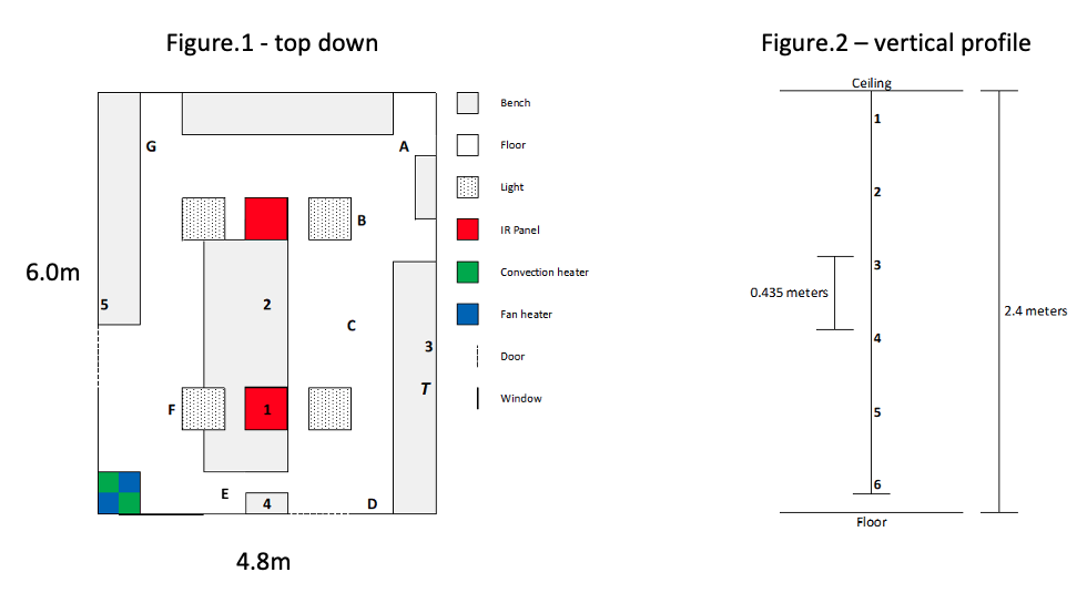
In Fig.1 numbers 1-5 represent the sensors placed on bench-tops with a 6th placed outside the lab (in an unheated ‘workshop’ area) to provide a ‘control’ base-line from an unheated zone within the same building. Letters A-G indicate the locations of the 7 strings that sensors were suspended from.
Fig.2 shows the arrangement of the 6 sensors on each of the strings, with sensors 1 and 6 being EL-USB-2 (temperature and humidity)and 2-5 being EL-USB-1 (temperature).
T (fig.1) represents a thermostatic controller, mounted at head height and ‘shaded’ so that it wasn’t directly irradiated by the IR energy. The controller was series wired with the heater(s) and was set to 17˚C in all tests. Also recorded was the voltage and current values supplying the respective heaters, using 2*UT60E multi-meters.
It should be recalled that the 2 self-standing heaters were floor standing, as per their respective designs, and positioned to give an ‘open’ aspect for the heated air to freely circulate around the room. The 2radiant heater panels were ceiling mounted to give their optimum angle of incidence around the full room, according to their designed best placing.
GeneralClimatic Conditions
Across the 3 days in question, local weather reports recorded the following data, which changed markedly from day-to-day during the test period:
Monday 19/04/2021(during fan heater trials): 1020 mbar pressure/ 33% RH/ wind SE 6.2mph/passing clouds/ temperatures through the day (a.m./ p.m./ evening) – highs 16oC-18oC-11oC – lows 15oC-16oC-11oC
Tuesday 20/04/2021(during convection heater trial): 1018 mbar pressure/ 51% RH/ wind N-NW 11.9mph passing clouds.Temperatures through the day (a.m./ p.m./ evening) - highs 15oC-17oC-15oC – lows8oC-15oC-11oC
Wednesday21/04/2021 (during IR heater trial): 1023 mbar pressure/ 59% RH/ wind E 10.6mph full cloud. Temperatures through the day (a.m./p.m./evening)- highs 14oC-14oC-14oC– lows 9oC-13oC-8oC
It will be noted that these outdoor temperatures varied appreciably from day-to-day, reaching respectively highs of 18oC& 17oC on the first 2 days but dropping sharply to only 13oCon day 3, when the IR panel heater was under test. Outdoor %RH varied considerably, but in the opposite direction (33%RH, 51%RH and 59%RH).
Temperature + %RH records inside 2DHeat building (in unheated workshop area) 5 metres from the laboratory test zone:
Despite the significantly varying outdoor temperatures and %RH levels recorded above, both the temperatures and %RH levels were recorded in the open workshop area adjacent to the laboratory; sensors were placed ~ 5m from the test-lab area, in a location shaded from direct sunlight. In this open workshop area the captured data showed steadily climbing temperatures throughout each individual test day with the rate of increase being similar for both the Monday and the Tuesday, but somewhat less steep for the (very significantly cooler) Wednesday.
For the related %RH figures for the open workshop area across the same 3 days, there was a relatively closer alignment across each of the 3 days than the widely varying external humidity levels would imply, suggesting that the workshop zone acts as a “moderating buffer-zone” between the lab test zone and the external weather conditions.
The above temperature data is shown in Graphs 1, 2 and 3 (below). Note that the label “Internal ambient” refers to the unheated workshop area, adjacent to the laboratory test area.
Graph 1: FAN heater
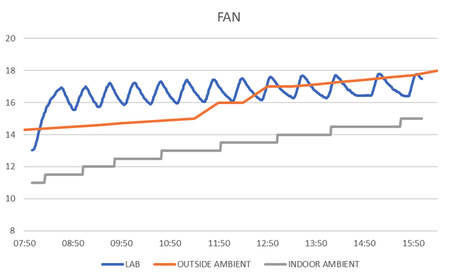
Graph 1: Temperatures recorded in lab/ workshop/ outdoors for fan heater trial
Aspects of note include that the 1st thermostat cut-out (set to 17oC)occurs at ~43 minutes. The external temperature climbs steadily all day long(as does the workshop temperature).
Graph 2: Temperatures recorded in lab/ workshop/ outdoors for convector heater trial
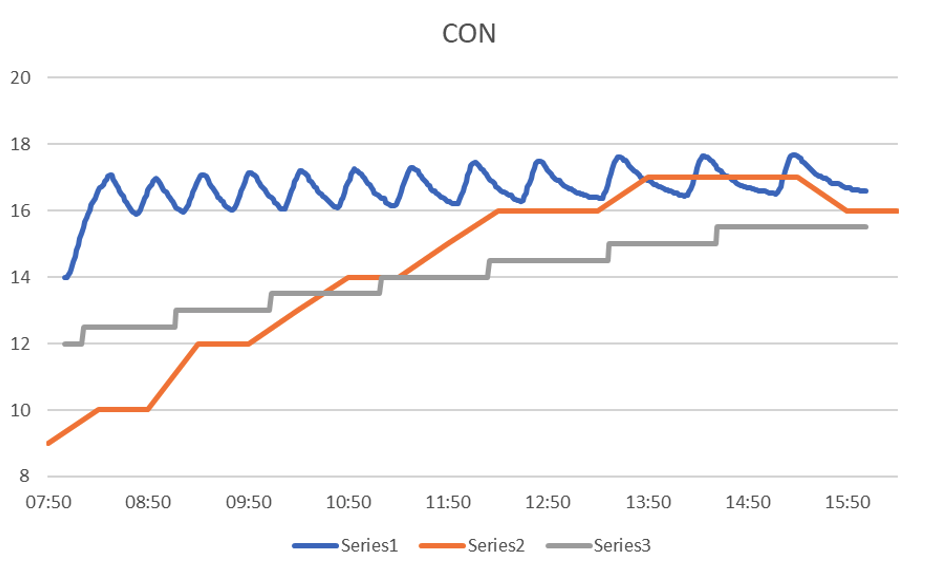
In Graph 2, Series1 denotes the average lab temperature. Series2 denotes the temperature external to the building. Series 3 denotes the workshop area temperature.
Aspects of note for the convector heater trial include that the 1st thermostat cut-out (set to 17oC) occurs at~35 minutes, which is faster than for the fan heater, even though the outdoors temperature is lower (& stays lower throughout the day, in spite of its upwards trajectory). However, the workshop temperatures during both of these trials were broadly similar, which would have served as an ‘attenuation’ factor that would reduce the impact of the more widely varying outdoor temperatures.
Graph 3: Temperatures recorded in lab/ workshop/ outdoors for Infra-Red heater trial
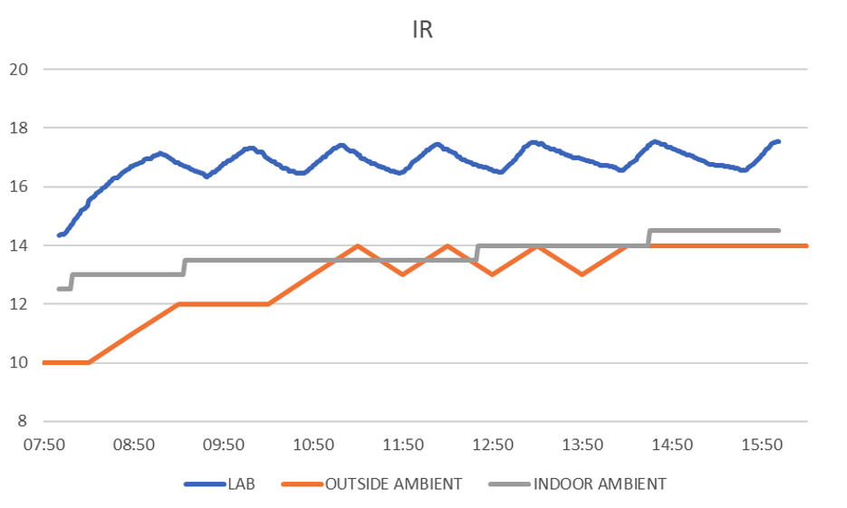
Aspects of note include that the 1st thermostat cut-out (set to 17oC)occurs at ~77 minutes, which prima facie appears to be considerably later than for both the convection heater and the fan heater, leading one to conclude that the IR heater is warming the room more slowly than the other two heaters – but this would be totally wrong! In fact, it is the reverse that applies. The following paragraph explains why.
Graph 4 superimposes onto Graph 3 the radiant heat flux present in the room during the IR heating trial, but which isn’t present for the other 2 heater types.
Graph 4:
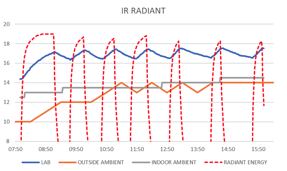
Understanding the area beneath the broken redline is critical, since this explains why the IR panel heater differs in speed of heating and efficiency versus both the fan and convection heaters.
In Graphs 1, 2& 3 the blue lines show the air temperature recorded inside the suspended heat sensors, but how that internal air is heated differs with the heater types. For the fan heater and for the convection heater it is the circulated hot air in the room in general that is the heat transfer medium. For the radiant heater it is the IR energy, shown by the broken red line, which is absorbed by the (relatively smooth ‘half-gloss’) black plastic body of the sensor which first heats up & which in turn progressively warms the internal air within each sensor. Despite being black in colour, the emissivity factor for that plastic sensor will be somewhat lower, (estimated emissivity factor ~0.80 based on the factor for black enamel paint), than for human skin, (emissivity factor 0.98 i.e – virtually an ideal ‘black body’ due to the huge number of surface ‘cavities’ & resultant surface area). The skin of the occupants in a room will accordingly respond to the near vertical rise in emitted radiant energy– the broken red line, whereas the small body shell of the temperature sensor picks up pro rata a lower quantum of IR energy than a person, but also responds less slowly to using that reduced level of energy because of the proportionally lower emissivity factor. This underpins, as ‘championed’ in case study 1, why measured temperature is NOT an appropriate factor to use when assessing the efficacy of IR room heaters. The(almost vertical) rise in radiant energy with 2DHeat’s “turbo” panels imparts, virtually like the sun emerging from behind a cloud, instant heat sensation to people in the room.
Later in the day, in those periods when the radiant energy heat is shut-off by the room thermostat, the level of retained body heat by the occupants can be projected to decline in line with the blue line shown for the sensors. So the integrated comfort factor is essentially shown by the hashed red line OR the blue line, whichever is the greater at any given moment in time.
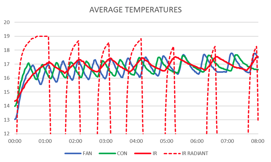
Accordingly, in graph5 (below) we show, super-imposed on each other, the average heating curves for all 3 heaters used in this study.
It is immediately apparent that the combined broken and solid red lines for the IR heater are more often higher than those for the fan and convection heaters. Remember too that the IR power input was only 1600W versus 2000W for each of the fan and convection heaters. Remember also that theIR trial was conducted on an appreciably cooler day (10oC-14o Crange) versus 14oC-18oC for the fan heater and 9oC-17oC for the convection heater.
Graph 5
ASHRAE Comfort factor impacts:
Considering the ‘comfort’ factor aspect, and the 7point ASHRAE scale[2]covered in Case Study 1 (see), the 2 operatives carrying out these trials independently assessed both the FAN heating and the CONVECTION heating to be equivalent to recurring swings between +1 and -1 ASHRAE score, as the temperature continually fluctuated between 18.7oC and 14.7oC for the fan heater, and between 19.7oC and 14.9oC for the convection heater. Alternatively, this was expressed by one of those operatives as +/- “1 hoodie”! Such a degree of ‘swing’ leads to a relative discomfiture factor to the human body.
As covered above, the corresponding figures for the IR heater panels spanned 18.1oC and 15.4oC, but this has no practical significance what-so-ever since the all-important ASHRAE comfort factor was assessed at +0.5 to 0, which represents an extremely constant level of room comfort.
In contrast, for the fan & convection heaters, the blue & green lines do show the rate at which the warmed air is circulated around the room and, via which, the room occupants are being warmed.Conversely, each time those fan & convection heaters switch off (via the room thermostat), the resulting (& much more frequent) falling heat input levels give rise to the relatively larger swings in perceived comfort levels associated with these types of heating.
The most striking aspect of the ‘in-lab’ temperature curves for both the fan and convection heaters is the way in which they fluctuated, across an approximate 1.5oC hysteresis zone, once the air temperature (at the thermostat) reached 17oC – the pre-set thermo-cut-out setting for the room thermostat. The IR panel heater, in contrast, reaches a cut-out value and the rate of air cooling is very much more attenuated, both in terms of duration and amplitude – nearer to 0.5oC.The switch-on point occurs at the trough of the hysteresis loop, when the virtually instantaneous radiative-energy heating benefit re-occurs, (as with the initial heat-up), even though the air temperature takes longer to recover.
In case study 2,(see), we further showed that the IR heater simply radiates heat energy ‘waves’ outwards from the panel heaters, uniformly in all directions, rather like ripples on a pond. This more uniformly heated the total room volume than did either the fan heater or the convection heater, adding to the sensation of greater comfort. In contrast, the more significant peaks & troughs for the fan & convection heaters result from their greater temperature variance across different areas of the room, according to where the fan heat is directed or from the location of the radiators giving rise to the warm-air thermal convection currents.
The Impact of dust & allergens circulated on warm air currents
Dust in the home or workplace is widely circulated on warm air currents and can be a major concern to room occupants when that dust contains organic matter including pollens and other common allergens, but also including sloughed-off dead skin, faecal residues from eg house dust mites, all capable of irritating the respiratory system of room occupants.
Not only fan heaters but also convection heaters(including like those tested in this study and also water filled radiators as in standard gas boiler fed central heating), work by continuously heating the air, causing it to rise, cool and fall generating a convection current in order to distribute the heat around the room. Whilst easily overlooked, these air currents also serve to circulate the dust, pollen and the other particulates and allergens referred to.
As shown in this study, the radiant heating effect of 2DHeat infrared panels not only produces a more even room heating, but does so without circulating the air, thereby avoiding the need for convection currents or fan blowers.
In contrast, where there is merit in using forced air ventilation, to refresh air supplies in a room when considering prevention of the spread of readily transmitted aerosol diseases, like covid 19, Case Study 4 (see) indicates the impact on IR room heating to be negligible since this doesn’t result in the loss of pre-heated air (such as the case with convection & fan heaters). Minimising heat losses via controlled ‘trickle’ ventilation is a positive consequence of this.
Relative humidity (%RH) and ventilation– comfort & health aspects
Humidity control and the degree of ventilation are other critical factors to consider when designing home heating comfort, as is the avoidance of localised condensation, mould growth and ultimately rot. The heating method used directly impacts each of these. The impact of IR not heating the air itself has already been well covered, thereby avoiding dust/ allergen circulation.
The relationship between relative humidity and air temperature is directly linked - as the air temperature increases so does the quantity of water vapour held within that air. Conversely, as the air temperature falls, that moisture content level decreases, with the water vapour condensing onto the coolest surfaces within cold spots in a room. This localised dew-point cycling is a precursor of mildew and/ or other fungal/ mould formations, the spores of which are spread on air currents. The relatively recent practice, of insulating buildings to exclude virtually all ventilation, whilst being good for energy conservation, has exacerbated condensational issues with consequential mould/ fungal problems – the fundamental reason to ventilate a building is moisture management & control, a critical factor to avoid accelerated building decay.
Humidity data was gathered during this testing usingEL-USB-2 temperature and humidity sensors, these sensors were in positions 1and 6 of each string (fig.2), the top and bottom sensors. Of the sensors placed on the benches (fig.1) sensor 5 inside the lab and sensor 6 recording ambient outside the lab also collected humidity data.
Graph ‘6’ shows the respective %RH variances with time(and air temperature) for all the suspended sensors in the room.
Graph 6 - relative humidity for all suspended sensors vs time.
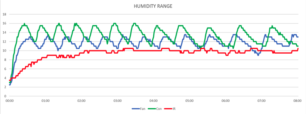
The most striking feature of the graphs is the way in which the %RH curves for both the fan and convection heaters constantly rise and fall with the room temperature; consequently more water vapour is being carried in the air – & capable of condensing out, (especially in the cooler, more remote corners). In contrast, the IR heated room demonstrates a steady %RH behaviour, since the air itself heats only slowly, via secondary convection heating, and only once the room fabric and furnishings start to pass heat into the air. In the first place, it is the fabric of the room (&furnishings) that heat them above the dew point, which also has the effect of drying any dampness form the walls, thus providing an environment less favourable to mould growth than convection or fan type heaters.
A further aspect of the 2DHeat Limited IR panel heaters is their hygienic ‘wipe-clean’ ceramic surface – the only caution being to ensure to do this only when the panels are NOT being heated and are cool!
Conclusions
Trials using 1.6 kW 2DHeat proprietary ‘turbo’ infrared heaters produce:
- An improved uniformity of room heating
- A reduced spread of temperature variations
- Reduced air movement & consequently dust circulation within a room
- A very much faster room ‘heat-up’ time (<5mins versus 35-43mins)
- A significantly abated increase in %RH, with nil hysteresis effect when at temperature when compared with a conventional 2kW fan heater or a2kW convection heater.
[1]See page 4 for details of ASHRAE scale
[2]+3 = much too warm
+2 = too warm
+1 = comfortably warm
0 = comfortable
-1 = comfortably cool
-2 = too cool
-3 = much too cool